API 661 AIR COOLER
API 661 Air fin coolers are mostly used to cool down processes that requires a huge amount of heat exchange. They are used mainly in the Oil & Gas and petrochemical industries but can also be found in power plants, mining and heavy industries. Air coolers offer a lot of advantages:
- The Cooling medium is air and is free (no need to cool water or have a secondary loop)
- Air is non-corrosive
- Can be installed on piperack or on the ground
- Low maintenance cost (compared to a cooling tower)
- Easy to assemble
Since 1960, D’HONDT THERMAL SOLUTIONS has been designing and manufacturing air coolers. D’HONDT THERMAL SOLUTIONS has installed over 10000 air coolers all over the world.
Our worldwide workers and engineers are dedicated to the design and manufacture of air coolers according to the latest and highest standards in order to meet the toughest operational requirements of our customers.
Moreover, D’HONDT THERMAL SOLUTIONS can offer an international network of products and services with factories/workshops in France, South Korea, Saudi Arabia and Russia. We are a major international air cooler manufacturer with a local presence. All our shops meet the same level of expectations and standards allowing us to handle very large, multi- plant locations projects to suit our customer needs and delivery times.
Principle
The principle of operation is very simple:
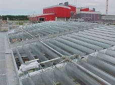
The process fluid is cooled while circulating inside finned tubes by the ambient air blown through the tube bundles by fans. The process fluid enters/exits the air coolers by respectively the inlet/outlet headers. The air coolers is made up of a bank of several finned tubes bundles in a “side by side” arrangement according to the overall heat output. The main benefit of using an air cooler is the elimination of an auxiliary water supply. Thus, air-cooled heat exchangers provide a lower environmental impact than shell and tube heat exchangers or cooling towers.
The air coolers are mainly composed of the following:
- Finned tubes bundles
- Motor & Fans
- Plenums
- Supporting steel structure
- Accessories
Configuration
Air coolers have 2 possible configurations:
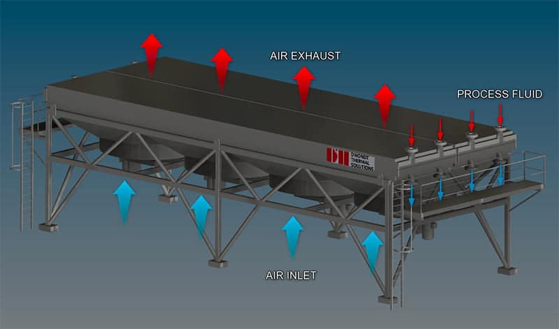
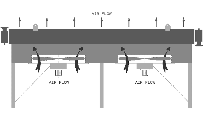
1. The air cooler is forced draft type:
This means that the fans are located below the bundles and the finned tube bundles are mounted on the top of a supporting steel structure. The fan rings air inlets (with/without inlet bell) are suspended to the plenums.
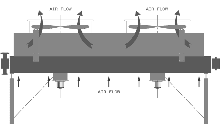
2. The air cooler is induced draft type:
This means that the fans are located above the bundles and the finned tube bundles are mounted on the top of a supporting steel structure. The fan rings air inlets (with/without inlet bell) are assembled above the plenums. The motors are below the bundles and the fan / motors connection is done with a shaft crossing the bundle.
Occasionally, the air cooler can be totally enclosed to create hot air recirculation. This special arrangement, called “winterization” is to maintain the air cooler in a – hotter than ambient air – environment to avoid freezing or pouring of the process medium during cold conditions.
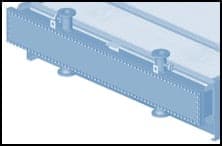
Finned tubes bundles
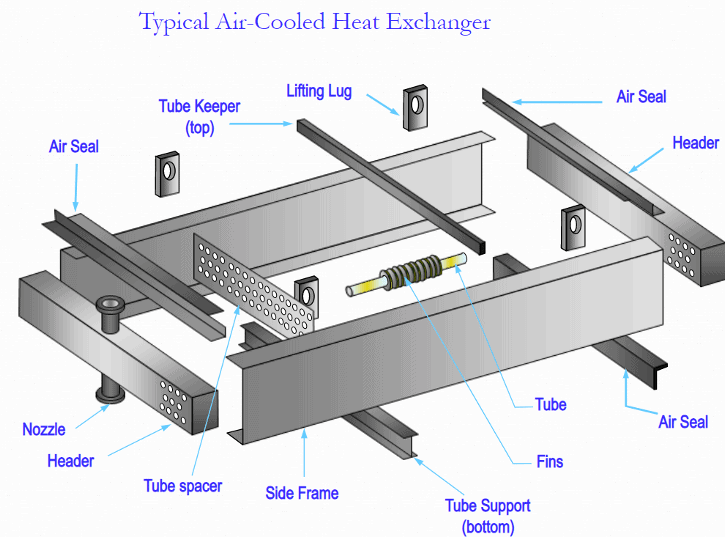
The finned tube bundle is made of 2 main parts:
1. The rectangular header
Headers are the boxes at the end of the tubes which distribute the fluid from the process piping to the tubes. Almost all headers are welded rectangular boxes. Headers are usually made of carbon steel or stainless steel but others steel alloys can occasionally be used.
3 types of header can be proposed:
A vast majority of the headers are of the plug type: There is a shoulder plug opposite each tube which allows access for inspection and cleaning of individual tubes. The plug hole will be used in the manufacturing process for access to expand the tubes into the headers and/or to weld the tube to the tube sheet.
Header with a removable bonnet (or cover plate) is also available. The front plate (or bonnet) can be removed for access and cleaning of the header box. This type can only be used for low-pressure application (below 30 bars)
Pipe Manifold and welded bonnet headers (non removable). Mainly used for steam coils or very high pressure.
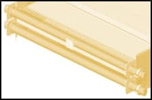
2. The finned tubes and their support
The tubes can be of any material available, such as carbon steel, stainless steel, or more occasionally, alloys as duplex or incoloy, depending on the fluid to be cooled and customer requirements. The minimum preferred outside diameter is one inch (1”). The tube wall thicknesses vary with the material and design pressure and temperature. The fins are made of aluminium material.
3 types of finned tubes are available:
KLM
The aluminum strip is formed in the same manner as the standard “L” fin with an additional step of knurling the fin’s foot to the tube. The knurling enhances both the mechanical contact and thermal transfer properties.
- Full protection of bare tube against corrosion.
- Successfully tested at service temperatures up to 320 ° C.
- Unique combination of high thermal performance and stress resistance with atmospheric corrosion protection.
- KLM can replace any type of finned tubes.
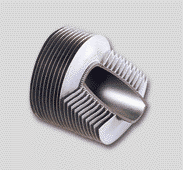
Embedded « G » type finned tubes
This design consists of an aluminum strip placed into a groove on the primary tube, tension wound on edge and finally maintained in place by the groove lip. This fin’s primary applications are high temperature or cyclic services.
- Provides a perfect bond between the fin and the tube.
- May be used at temperatures up to 400°C
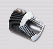
Extruded finned tubes
Primarily used in corrosive atmospheres and high temperature conditions, the extruded fin is manufactured by compressing an aluminum sleeve onto a parent tube. High compression reforms the aluminum into the final fin profile.
- Full protection of bare tube against corrosion
- High mechanical strength of fins.
- May be used at temperature up to 300°C
The finned tubes are held in position by the tube holders and the tube keepers. Spacers are used to maintain the tube in the right position without damaging the fins. They allow direct contact between tubes or between a tube and a tube supporting beam.

Motors & Fans
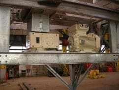
1. Motors
Positioned below the bundle, it drives its corresponding fan. The coupling Motor/fan can be:
- direct
- through a gear box speed-reducing transmission system
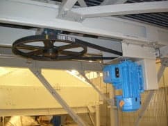
- through a belt-type speed-reducing transmission system
The motors can also function in:
- on/off mode
- with a dual speed system
- coupling with a variable speed drive (VSD)
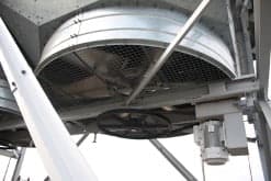
2. Fans
Each Fan (axial type) is running inside a fan ring. Fan blades are usually made of Aluminum but can also be made of FRP. The pitch angle can be adjustable at standstill or automatically set during operation (AV fans). Protection grids are added and attached to the fan ring and the motor support beam for safety reason (personal and equipment protections).
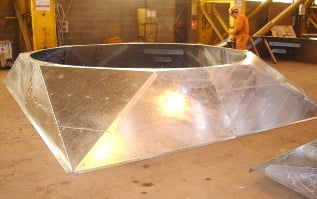
Plenums
Plenums are Conical/rectangular shaped steel structures that help diffuse the air flow through the complete finned surface. They are placed between the bundle and the fan ring.
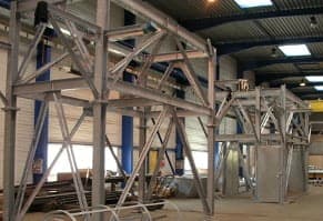
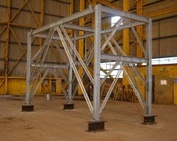
Supporting steel structure
The supporting steel structure maintains the air coolers in a position where hot air recirculation must be avoided. Its design depends on the air cooler’s surroundings, customer requirements and site data (earthquake, hurricanes…)
Accessories
Various accessories can be added to our air coolers:
- Separate steam coil below the bundle (to preheat the ambient air)
- Louvers (manually or automatically operated)
- Vibration switches/sensors
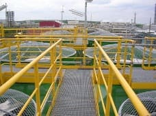
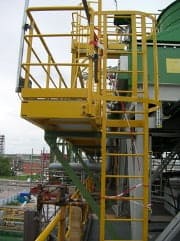
- Header access walkways
- Motor/Fan access walkways
- Other accessories on demand (subject to technical feasibility)